F-Layer Propagation
The region of the F layers, from 150 km (90 mi) to over 400 km (250 mi) altitude, is by far the most important for long-distance HF communications. F-region oxygen atoms are ionized primarily by ultraviolet radiation. During the day, ionization reaches maxima in two distinct layers. The F1 layer forms between 150 and 250 km (90 and 160 mi) and disappears at night. The F2 layer extends above 250 km (160 mi), with a peak of ionization around 300 km (190 mi). At night, F-region ionization collapses into one broad layer at 300-400 km (190-250 mi) altitude. Ions recombine very slowly at these altitudes, because molecular density is relatively low. Maxi- mum ionization levels change significantly with time of day, season and year of the solar cycle.
F1 Layer
The daytime F1 layer is not important to HF communication. It exists only during daylight hours and is largely absent in winter. Radio signals below 10 MHz are not likely to reach the F1 layer, because they are either absorbed by the D layer or refracted by the E layer. Signals higher than 20 MHz that pass through both of the lower ionospheric regions are likely to pass through the F1 layer as well, because the F1 MUF rarely rises above 20 MHz. Absorption diminishes the strength of any signals that continue through to the F2 layer during the day. Some useful F1-layer refraction may take place between 10 and 20 MHz during summer days, yielding paths as long as 3000 km (1900 mi), but these would be practically indistinguishable from F2 skip.
F2 and Nighttime F Layers
The F2 layer forms between 250 and 400 km (160 and 250 mi) during the daytime and persists throughout the night as a single consolidated F region 50 km (30 mi) higher in altitude. Typical ion densities are the highest of any ionospheric layer, with the possible exception of some unusual E-layer phenomenon. In contrast to the other ionospheric layers, F2 ionization varies considerably with time of day, season and position in the solar cycle, but it is never altogether absent. These two characteristics make the F2 layer the most important for long- distance HF communications.
The F2-layer MUF is nearly a direct function of UV solar radiation, which in turn follows closely the solar cycle. During the lowest years of the cycle, the daytime MUF may climb above 14 MHz for only a few hours a day. In contrast, the MUF may rise beyond 50 MHz during peak years and stay above 14 MHz throughout the night. The virtual height of F2 averages 330 km (210 mi), but varies between 200 and 400 km (120 and 250 mi). Maximum one-hop distance is about 4000 km (2500 mi), but it may be effectively longer when the MUF is above 40 MHz. Near-vertical incidence skywave propagation just below the critical frequency provides reliable coverage out to 200-300 km (120-190 mi) with no skip zone. It is most often observed on 7 MHz during the day.
In general, both F2-layer ionization and MUF build rapidly at sunrise, usually reach a maximum in the afternoon, and then decrease to a minimum prior to sunrise. Depending on the season, the MUF is generally highest within 20° of the equator and lower toward the poles. For this reason, transequatorial paths may be open at a particular frequency when all other paths are closed.
In contrast to all the other ionospheric layers, daytime ionization in the winter F2 layer averages four times the level of the summer at the same period in the solar cycle, doubling the MUF. This so-called winter anomaly is caused by the Earth moving closer to the Sun and tilting. Wintertime F2 conditions are much superior to those in summer, because the MUF is much higher.
Multihop F-Layer Propagation
Most HF communication beyond 4000 km (2500 mi) takes place via multiple ionospheric hops. Radio signals are reflected from the Earth back toward space for additional ionospheric refractions. A series of ionospheric refractions and terrestrial reflections commonly create paths halfway around the Earth. Each hop involves additional attenuation and absorption, so the longest-distance signals tend to be the weakest. Even so, it is possible for signals to be propagated completely around the world and arrive back at their originating point. Multiple reflections within the F layer may bypass ground reflections alto- gether, creating what are known as chordal hops, with lower total attenuation. It takes a radio signal about 0.15 second to make a round-the-world trip.
Multihop paths can take on many different configurations, as shown in the examples of Fig 21.17. E-layer (especially sporadic E) and F-layer hops may be mixed. In practice, multihop signals arrive via many different paths, which often increases the problems of fading. Analyzing multihop paths is com- plicated by the effects of D- and
E-layer absorption, possible
reflections from the tops of sporadic-E layers, disruptions in the auroral zone and other phenomena.
F-Layer Long Path
Most HF communication takes place along the shortest great-circle path between two stations. Short-path propaga- tion is always less than 20,000 km (12,000 mi)—half- way around the Earth. Never- theless, it may be possible at times to make the same contact in exactly the opposite direc- tion via the long path. The long-path distance will be 40,000 km (25,000 mi) minus the short-path length. Signal strength via the long path is usually considerably less than the more direct short-path. When both paths are open si- multaneously, there may be a
Fig 21.17—Multihop paths can take many different configura- tions, including a mixture of E- and F-layer hops. (A) Two F- layer hops. Five or more consecutive F-layer hops are possible. (B) An E-layer hookup to the F layer. (C) A top-side E-layer reflection can shorten the distance of two F- layer hops. (D) Refraction in the E layer above the MUF is insufficient to return the signal to Earth, but it can go on to be refracted in the F layer. (E) The Pedersen ray, which originates from a signal launched at a relatively high angle above the horizon into the E or F region, may result in a single-hop path, 5000 km (3100 mi) or more. This is considerably further than the normal 4000- km (2500 mi) maximum


 F-region
single-hop distance, where the signal is launched at a very low
takeoff angle. The Pedersen ray can easily be disrupted by any sort of
iono- spheric gradient.

distinctive sort of echo on received signals. The time interval of the echo represents the difference between the short-path and long-path distances.
Sometimes there is a great advantage to using the long path when it is open, because signals can be stronger and fading less troublesome. There are times when the short path may be closed or disrupted by E-layer blanketing, D-layer absorption or F-layer gaps, especially when operating just below the MUF. Long paths that predominantly cross the night side of the Earth, for example, are sometimes useful because they generally avoid blanketing and absorption problems. Daylight-side long paths may take advantage of higher F-layer MUFs that occur over the sunlit portions of the Earth.
F-Layer Gray-Line
Gray-line paths can be considered a special form of long-path propagation that take into account the unusual ionospheric configuration along the twilight region between night and day. The gray line, as the twilight region is sometimes called, extends completely around the world. It is not precisely a line, for the distinction between daylight and darkness is a gradual transition due to atmospheric scattering. On one side, the gray line heralds sunrise and the beginning of a new day; on the opposite side, it marks the end of the day and sunset.
The ionosphere undergoes a significant transformation between night and day. As day begins, the highly absorbent D and E layers are recreated, while the F-layer MUF rises from its pre-dawn minimum.
 At the end of the
day, the D and E layers quickly disappear, while the F-layer MUF
continues its slow decline from late afternoon. For a brief period just
along the gray-line transition, the D and E layers are not well formed,
yet the F2 MUF usually remains higher than 5 MHz. This
provides a special opportunity for stations at 1.8 and 3.5 MHz.
Normally, long-distance communication on the lowest two amateur bands can take place only via all-darkness paths because of daytime D-layer absorption. The gray-line propagation path, in contrast, extends completely around the world. See Fig 21.18. This unusual situation lasts less than an hour at sunrise and sunset when the D-layer is largely absent, and may support contacts that are difficult or impossible at other times.
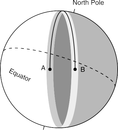
The gray line generally runs north-south, but it varies by 23º either side of true north as measured at the equator over the course
of the year. This variation is caused by the tilt in the Earth’s axis. The gray line is exactly north-south through the poles at the equi- noxes (March 21 and September 21) and is at its 23º extremes on June 21 and December 21. Over a one-year period, the gray line crosses a 46º sector of the Earth north and south of the equator, providing optimum paths to slightly different parts of the world each day. Many commonly available computer programs plot the gray line on a flat map or globe. The ARRL Operating Manual provides sunrise and sunset times over the entire year for several hundred worldwide locations. The position of the gray line on any date can also be plotted manually on a globe from these data.
F-Layer Backscatter and Sidescatter
Special forms of F-layer scattering can create unusual paths within the skip zone. Backscatter and sidescatter signals are usually ob-
Fig 21.18—The gray line encircles the Earth, but the tilt at the equator to the poles varies over 46° with the seasons. Long- distance contacts can often be made halfway around the Earth along the gray line, even as low as 1.8 and 3.5 MHz. The strength of the signals, characteristic of gray-line propagation, indicates that multiple Earth-ionosphere hops are not the only mode of propagation, since losses in many such hops would be very great. Chordal hops, where the signals are confined to the ionosphere for at least part of the journey, are involved.
served just above the MUF for the direct path and allow communications not normally possible by other means. They also provide a useful clue to propagation conditions, because reception of backscatter or sidescatter signals suggests that the MUF is just below the operating frequency. Backscattered signals are generally weak and have a characteristic hollow sound. Useful communication distances range from 100 km (60 mi) to the normal one-hop distance of 4000 km (2500 mi).
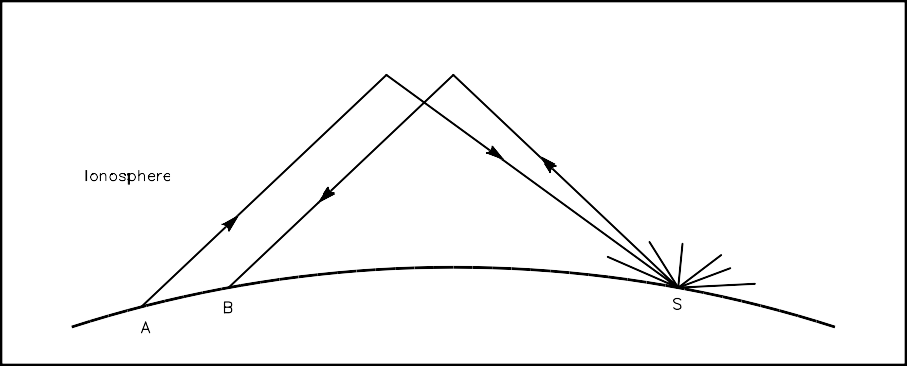
Backscatter and sidescatter are closely related and the terminology does not precisely distinguish between the two. Backscatter usually refers to single-hop signals that have been scattered by the Earth or the ocean at some distant point back toward the transmitting station. Two stations spaced a few hundred km apart can often communicate via a backscatter path near the MUF. See Fig 21.19.
Sidescatter usually refers to a circuit that is oblique to the normal great-circle path. Two stations can make use of a common side-scattering region well off the direct path, often toward the south. European and North American stations sometimes complete 28-MHz contacts via a scattering region over Africa. US and Finnish 50-MHz operators observed a similar effect early one morning in November 1989 when they made contact by beaming
 off
the coast of West Africa.
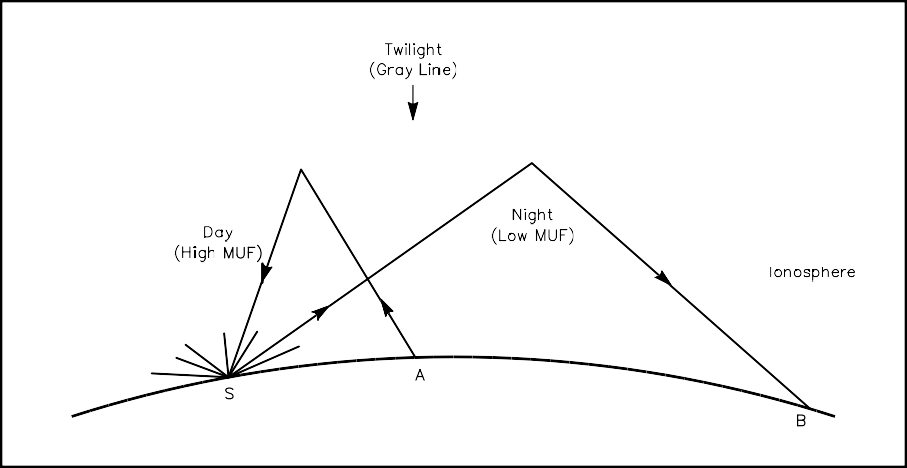
When backscattered signals cross an area where there is a sharp gradient in ionospheric density, such as between night and day, the path may take on a different geometry, as shown in Fig 21.20. In this case, stations can communicate because backscattered signals return via
the day side ionosphere on a shorter hop than the night side. This is possible because the day- side MUF is higher and thus the skip distance shorter. The net effect is to create a backscatter path between two stations within the normal skip zone.
Transequatorial Spread-F
Discovered in 1947, trans- equatorial spread-F (TE) sup- ports propagation between 5000 and 8000 km (3100 and 5000 mi) across the equator from 28 MHz to as high as 432 MHz. Stations attempting TE contacts must be nearly equidistant from the geomag- netic equator. Many contacts have been made at 50 and 144 MHz between Europe and South Africa, Japan and Aus- tralia and the Caribbean region
Fig 21.19—Schematic of a simple backscatter path. Stations A and B are too close to make contact via normal F-layer ionospheric refraction. Signals scattered back from a distant point on the Earth’s surface (S), often the ocean, may be accessible to both and create a backscatter circuit.

Fig 21.20—Backscatter path across the gray line. Stations A and B are too close to make contact via normal ionospheric refraction, but may hear each other’s signals scattered from point S. Station A makes use of a high-angle refraction on the day side of the gray line, where the MUF is high. Station B makes use of a night-time refraction, with a lower MUF and lower angle of propagation. Note that station A points away from B to complete the circuit.
and South America. Fewer contacts have been made on the 222-MHz band. TE signals have been heard at 432 MHz, but so far, no two-way contacts have resulted.
Unfortunately for most continental US stations, the geomagnetic equator dips south of the geographic equator in the Western Hemisphere, as shown in Fig 21.21, making only the most southerly portions of Florida and Texas within TE range. TE contacts from the southeastern part of the country may be possible with Argentina, Chile and even South Africa.
Transequatorial spread-F peaks between 5 PM and 10 PM during the spring and fall equinoxes, especially during the peak years of the solar cycle. The lowest probability is during the summer. Quiet geomagnetic conditions are required for TE to form. Signals have a rough aurora-like note, sometimes termed flutter fading. High power and large antennas are not required to work TE, as VHF stations with 100 W and single long Yagis have been successful.
The best explanation of TE propagation suggests that the F2 layer near the equator bulges and inten- sifies slightly, particularly during solar maxima. Irregular field-aligned ionization forms shortly after sunset in an area 100-200 km (60-120 mi) north and south of the geomagnetic equator and 500-3000 km (310-1900 mi) wide. For this reason, the mode is sometimes called transequatorial field-aligned irregu- larities. It moves west with the setting sun. The MUF may increase to twice its normal level 15º either side of the geomagnetic equator.
Field alignment of ionospheric irregularities favors refraction along magnetic field lines, that is north- south. VHF and UHF signals are refracted twice over the geomagnetic equator at angles that normally would be insufficient to bring the signals back toward Earth. See Fig 21.22. The geometry is such that two shallow reflections in the F2 layer can create north-south terrestrial paths up to 8000 km (5000 mi). Spread-F propagation also occurs over the polar regions, but because of low population densities, amateurs have rarely reported making use of it. Near the northern magnetic pole (located in extreme northeastern Canada), spread-F is a nearly permanent feature of winter. During summer, it appears most summer nights and at least half the time during the day. There is a greater probability of polar

Fig 21.21—Transequatorial spread-F propagation takes place between stations equidistant across the geomagnetic equator. Distances up to 8000 km (5000 mi) are possible on 28 through 432 MHz. Note the geomagnetic equator is considerably south of the geographic equator in the Western Hemisphere.

Fig 21.22—Cross-section of a transequatorial spread-F signal path, showing the effects of ionospheric bulging and a double refraction above the normal MUF.
spread-F appearing during the equinox periods and during the solar cycle maximum. Field- alignment in the polar regions suggests that some form of backscatter signals, similar to aurora, would be most likely.
